Running DOS on Behringers DDX3216 with a DIY x86-Bios from Scratch
Source: Hacker News
In 1994 I got my first computer: an Intel i486 DX2-66 with 4 MB RAM and a 512MB harddisk. The software was IBMs OS/2 and Microsofts Windows 3.11. In the next four years I was upgrading this machine every few months with more RAM (up to 16MB), a CD-ROM-drive and a soundblaster card. So I learned upgrading this machine, installing new software and finally learned how to program new software using BASIC. But I never got in touch with the boot-process or the details of MS-DOS.
In 2026, 32 years later, I learned from some screenshots of the DDX3216, that Behringer used a real 386 processor within this machine. Immediately, some of my neurons fired in my head and I pondered if I could boot software and even a full operating system on this device. My goal was to learn how an x86-system is booting, how DOS takes over and what is necessary to get into the shell.
Table of Contents
Technical Details of the Behringer DDX3216
First steps developing own software for bare-metal x86
Getting the LCD up and running – and struggling with Segments
Implementing a full-featured x86 BIOS for the SC300
Interrupt-functions and trying to boot MS-DOS 6.22
Successfully booting FreeDOS v1.4
More internal hardware and next steps
Technical Details of the Behringer DDX3216
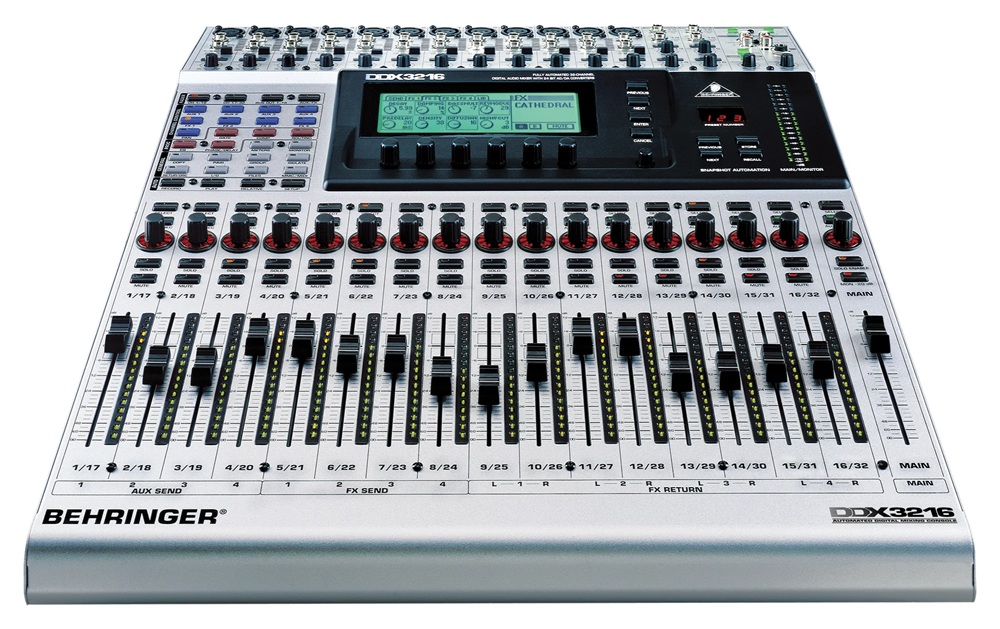
The DDX3216 uses the following hardware-components:
-
Main-Processor: AMD Elan SC300 386 SoC (386SX with integrated UART, PCMCIA, GPIO, etc.)
-
27C512 64k x 8bit ROM IC (for BIOS)
-
8x HYB5117400BJ60 4M x 4bit RAM for total of 16MB DRAM
-
1x UM61256 SRAM (as Video-RAM)
-
4x 29C040-120 Flash-ICs for the main-software
-
4-bit LCD on SC300-internal LCD-interface (with 3x Toshiba T6A39 Col- and 1x T6A40 Row-Controller)
-
Toshiba TLC16C552 external UART (2 Serial-ports and 1x parallel port)
-
PCMCIA-Connector for external CF-card-connection (with adapter)
-
unassembled Intel 82078 FDC (Floppy Disk Controller) connected to a spare 34-pin connector
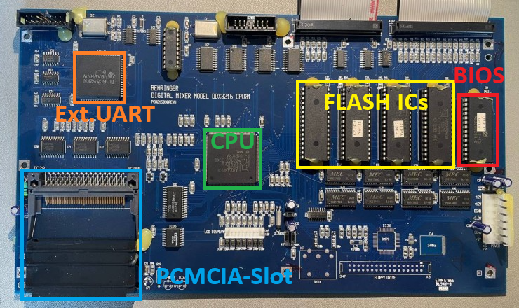
So in summary the hardware around the AMD Elan SC300 is pretty nice and should be compatible to a regular x86-system. Lets deep dive into the x86-system in detail.
For most computers you can download a ready-to-use BIOS from the internet. So I searched for a BIOS for the AMD ELAN SC and found a promising device in switzerland: the company PC Engines developed BIOS-programs for the AMD ELAN SC400 and 520 as well as some more SoC-devices. So I got in contact with the main-developer and first he gave a promising answer that he still has the sourcecode for the SC300. But a couple of days later he had to admit, that he only has sources from the SC400 upwards. My next try was to get in contact with the compancy “General Software” that offered the “Embedded BIOS” with support for the SC300. But General Software, founded in 1989, has been aquired by Phoenix in 2008. So I got in contact with one of the responsible persons of Phoenix in Germany. He tried to get some information about an SC300-compatible BIOS-package, but after a couple of weeks he had to tell me that its not possible anymore – 32 years are a long time.
So, I rolled up my sleeves and started reading some documentations about the x86-system and made some notes on programming my own BIOS for the SC300. Even the most-modern x86-compatible CPUs like Intels Core i9 or the AMDs Threadripper have an 8086-compatible boot-process. Directly after the reset, the CPU jumps to the end of the memory-space at the position 0xFFF0 and expects some executable x86 code here – the so called reset-vector. From this reset-vector we have to jump to the desired code that should be executed next – somewhere in the ROM of the BIOS.
Here is my attempt of implementing a valid x86-reset-vector:
ASM
reset_vector:
    nop                         // no-operation
    cli                         // disable interrupts
    jmp start                   // jump to beginning of current segment

    // Padding to the end and add date
    .zero (0x10 - (. - reset_vector) - 8)
    .ascii "06/04/26"           // MM/DD/YY
This code disables the hardware-interrupts and then jumps to more code in the start-function. By executing this jump-command, the CPU leaves the startup-state and enters the so called “real-mode”, the original 16-bit mode of the 8086. The code of the reset vector is placed by the linker-script to the position 0xFFF0 of the final ROM. As you can see in the list above, the DDX3216 uses a 64k x 8bit ROM-Chip, so code and data can be stored somewhere between 0x0000 and 0xFFFF, while the reset-vector has to be placed at 0xFFF0 to be compatible to the x86-cpecifications. Here is the linker-script to tell GCC how to place the code in the final binary-file:
Plaintext
OUTPUT_FORMAT("elf32-i386")
OUTPUT_ARCH(i386)
ENTRY(reset_vector)

MEMORY {
    ROM (rx)  : ORIGIN = 0x0000, LENGTH = 64K
}

SECTIONS {
    .text : {
        __text_start = .;
        KEEP(*(.text))
        *(.text.*)
        . = ALIGN(2);
        __text_end = .;
    } > ROM

    .reset 0xFFF0 : {
        KEEP(*(.reset))
    } > ROM
}
Finally, the compiled binary looks like this:
Plaintext
0000ffa0 00 00 00 00 00 00 00 00 00 00 00 00 00 00 00 00 ................
0000ffb0 00 00 00 00 00 00 00 00 00 00 00 00 00 00 00 00 ................
0000ffc0 00 00 00 00 00 00 00 00 00 00 00 00 00 00 00 00 ................
0000ffd0 00 00 00 00 00 00 00 00 00 00 00 00 00 00 00 00 ................
0000ffe0 00 00 00 00 00 00 00 00 00 00 00 00 00 00 00 00 ................
0000fff0 90 fa e9 0b 00 00 00 00 30 36 2f 30 34 2f 32 36 .úé.....06/04/26
So we see a 0x90 at 0xFFF0 which is a “nop” (No Operation), an 0xFA, which is the “cli” to disable all interrupts followed by an 0xE9 which is the jump-instruction. 0x0B is the near-address the jump-command has to jump to. “Near” means, this address is within the current segment. Well, segments are a special thing in the x86-system: as we have only 16-bits, we could address only 65535 bytes. To address more addresses, the x86 uses 64k-Segments to address more data. The problem: to stay backwards-compatible, the segment-address-pointers overlap each other by 16 bytes. This allows addressing of 0xFFFF segments every 16 bytes, resulting in an address-room of 0x00000 to 0xFFFF0, hence 1 MB. The physical address is calculated by the following equation:
Plaintext
Physical Address = (SEGMENT >  8) & 0xFF));  // 0x1F4
    outb(IDE_LBA_HIGH,    (uint8_t)((lba >> 16) & 0xFF));  // 0x1F5
    outb(IDE_DRIVE_HEAD,  0xE0 | ((lba >> 24) & 0x0F));    // 0x1F6
    outb(IDE_COMMAND,     IDE_CMD_READ);  // 0x1F7

    // wait until data is ready (DRQ set)
    if (!ide_wait_drq()) {
        return 0xBB;  // ERROR: DRQ timeout
    }

    // read 512 bytes data (one full sector)
    // is delivered at IO-address 0x1F0 (IDE_DATA-register)
    for (uint16_t i = 0; i  0) {
        if (ide_read_bootsector() == 0x00) {
            status = 0; // success
            break;
        }
        // error reading -> retry
    }

    if (status != 0) {
        // ERROR: read after 3 retrys
        return;
    }

    // check boot-signature at the end of the MBR
    uint16_t signature = readFarWord(BASE_SEG, 0x7C00 + 510);
    if (signature != 0xAA55) {
        // ERROR: no valid magic word
        return;
    }

    // bootsector seems to be fine -> jump to bootsector
    launch_bootsector();
}
The function launch_bootsector() is an assembler-function and looks like this – it simply resets the segment-registers, sets an initial stack right below the bootsector, selects the bootdrive using register DX and performs a far-jump to the begin of the bootsector:
ASM
launch_bootsector:
    cli                         ; disable interrupts

    ; clear all segments to 0x0000
    xor ax, ax                  ; set ax to 0x0000
    mov ds, ax
    mov es, ax

    ; set stack-pointer for initial DOS
    ; right below bootsector at 0x0000:0x7C00
    mov ss, ax                  ; set Stack-Segment to 0x0000
    mov sp, 0x7C00

    ; write the boot-drive to DL
    mov dl, 0x80

    sti                         ; enable interrupts again

    ; far-jump to bootsector
    jmp 0x0000:0x7C00
After compiling and uploading everything, I plugged in the CF card and booted the system.. but nothing happened. I debugged the interrupt-calls using the UART-interface and found that some of my interrupt-functions had some troubles with wrong function-codes and responses back to DOS. I fixed the specific interrupts and then booted up again. Still the LCD did not show any information from DOS, but much more INT 0x13 get called. But suddenly the system crashed again.
On the UART-interface I printed the stackpointer and found out, that the stack went very low – even though I started the stack right below 0x7C00. The reason is that the stack is growing from top to bottom, but when the stackpointer is getting too low this means the stack has some trouble. Obviously DOS is either rearranging the stack or is using huge amount of the stack (turns out DOS is moving the stack to a lower part in memory to get more free RAM). So I spent some hours reorganizing my memory-model and spent a separate BIOS-stack at the top of the conventional memory just for the BIOS-interrupt-calls. This did the trick and DOS went much further. As you can see in the next picture “Starting MS-DOS…” is showing up, followed by some more interrupt-calls:
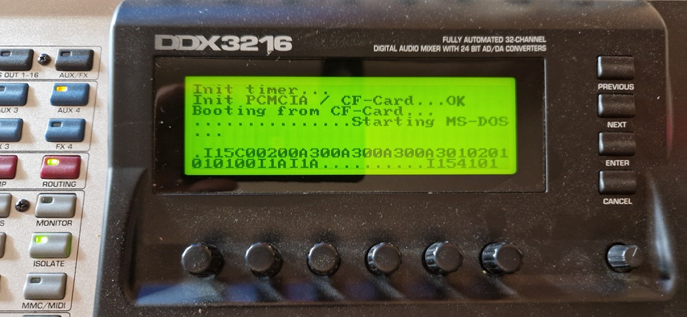
After the “Starting MS-DOS…” text, interrupt 0x15 is called, following by some INT 0x1A (RTC-clock). The dots indicates calls to INT 0x13 (disk-reading) but the system hangs after calling INT 0x15 a last time with AX = 0x4101, which is not a regular function-call. So DOS seems to give up after trying to read some sectors. I tried several days to get this under control, but at some point I gave up… I was so close to the DOS-shell. Looking into the MS-DOS 4.0 sourcecode, IO.SYS and MSDOS.SYS seems to be loaded successfully as the RTC-interrupt already get called. So somewhere between MSDOS.SYS and COMMAND.COM the system get stuck. Even by looking at the sourcecode of MS-DOS 4.0 which has been published by Microsoft, I couldn’t find the culprit up to now. So I gave up on MS-DOS 6.22 for now.
Successfully booting FreeDOS v1.4
As MS-DOS 6.22 was not starting I downloaded the most recent version of FreeDOS which was version 1.4. I fired up QEMU and created a small virtual environment to install FreeDOS:
BAT (Batchfile)
rem Create new virtual image for FreeDOS
qemu-img create -f raw freedos.img 100M

rem Start the system with FreeDOS LiveCD
rem virtual disk with 203 cylinders, 16 heads and 63 sectors
qemu-system-i386 -machine isapc -cpu 486 -m 8 -device isa-vga,vgamem_mb=1 -rtc base=localtime -drive file=freedos.img,format=raw,if=none,id=d1 -device ide-hd,drive=d1,cyls=203,heads=16,secs=63 -cdrom FD14LIVE.iso -boot d

rem Alternative:
rem Start the system with MS-DOS 6.22 Boot-Floppy
rem virtual disk with 203 cylinders, 16 heads and 63 sectors
qemu-system-i386 -machine isapc -cpu 486 -m 8 -device isa-vga,vgamem_mb=1 -rtc base=localtime -drive file=freedos.img,format=raw,if=none,id=d1 -device ide-hd,drive=d1,cyls=203,heads=16,secs=63 -fda dos622.img -boot a
After the install-process I used Rufus to copy the virtual image sector by sector to the real CF-card. I then moved to the Behringer DDX3216 audiomixing console and booted the system:
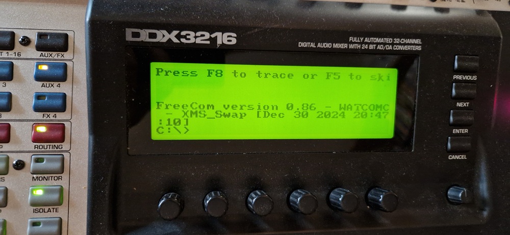
Wow – FreeDOS did finally the trick. After a total of three weeks I managed to create a DIY BIOS compatible enough with real x86-software that I was able to boot a real operating system. I still have to implement some more code for interrupt 0x16 (keyboard-access) as well as some minor stuff, but in general the system is up and running.
More internal hardware and next steps
Lot of components in the DDX3216 are strictly based on logic ICs. For instance all LEDs are controlled using a basic shift-register connected to the IO-interface of the SC300. First the control-signals are fed into IC5A and IC6A while IC5A controls signals VULTCH, LSSELR, UCSELR and SPTESR and IC6A controls signals VUSELW, LSSELW, UCSELW, LSLTCH, FLSET1, FLSET0. The Addressbits SA12..15 of the SC300 are used on the IO-bus, resulting in an address-space between 0x1000 and 0xF000. 0x3000 will enable VUSELW on writing and VULTCH on reading the IO bus. So LEDs 1 and 9 of Audio-Channel 1-4 are controlled at address 0x3000 bit 0, LEDs 8 and 16 of Channel 1-4 at address 0x3000 bit 7. Four more shift-registers are connected to the 9th bit of the previous shift-register so that the bits are shifted through multiple logic ICs as well.
Furthermore to limit the maximum current of the VCC or GND pins of the LED-drivers, the even and odd LEDs are connected to GND and VCC alternately:
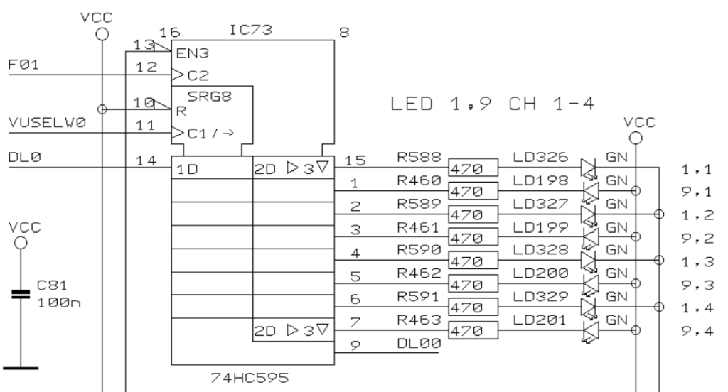
So, we have to send 0 and 1 depending on the selected LED in the shift-register. The following code sets all VU-meter-LEDs of all channels to HIGH:
C
bool even = false;
for (uint8_t i = 0; i < (8 * 5); i++) {
    if (even) {
        outb(0x3000, 0b11111111);
    }else{
        outb(0x3000, 0b00000000);
    }
    inb(0x3000);

    even = !even;
}
The code works because we have five concatenated 8-bit-shift-registers with alternating LEDs on each output. Each bit of the above byte is connected to a specific LED. Here is a full list of the VU-meter LEDs:
C
// DL30..37
outb(0x3000, 0b00000000); inb(0x3000); // led 1, Left   led 2, Left     led 3, Left
outb(0x3000, 0b11111111); inb(0x3000); // led 9, Left   led 10, Left    led 11, Left
outb(0x3000, 0b00000000); inb(0x3000); // led 1, Right  led 2, Right    led 3, Right
outb(0x3000, 0b11111111); inb(0x3000); // led 9, Right  led 10, Right   led 11, Right
outb(0x3000, 0b00000000); inb(0x3000); // LED-segment
outb(0x3000, 0b00000000); inb(0x3000); // LED-segment
outb(0x3000, 0b00000000); inb(0x3000); // LED-segment
outb(0x3000, 0b00000000); inb(0x3000); // free

// DL20..27
outb(0x3000, 0b00000000); inb(0x3000); // led 1, ch 13   led 2, ch 13    led 3, ch 13
outb(0x3000, 0b11111111); inb(0x3000); // led 9, ch 13   led 10, ch 13   led 11, ch 13
outb(0x3000, 0b00000000); inb(0x3000); // led 1, ch 14   led 2, ch 14    led 3, ch 14
outb(0x3000, 0b11111111); inb(0x3000); // led 9, ch 14   led 10, ch 14   led 11, ch 14
outb(0x3000, 0b00000000); inb(0x3000); // led 1, ch 15   led 2, ch 15    led 3, ch 15
outb(0x3000, 0b11111111); inb(0x3000); // led 9, ch 15   led 10, ch 15   led 11, ch 15
outb(0x3000, 0b00000000); inb(0x3000); // led 1, ch 16   led 2, ch 16    led 3, ch 16
outb(0x3000, 0b11111111); inb(0x3000); // led 9, ch 16   led 10, ch 16   led 11, ch 16

// DL10..17
outb(0x3000, 0b00000000); inb(0x3000); // led 1, ch 9    led 2, ch 9     led 3, ch 9
outb(0x3000, 0b11111111); inb(0x3000); // led 9, ch 9    led 10, ch 9    led 11, ch 9
outb(0x3000, 0b00000000); inb(0x3000); // led 1, ch 10   led 2, ch 10    led 3, ch 10
outb(0x3000, 0b11111111); inb(0x3000); // led 9, ch 10   led 10, ch 10   led 11, ch 10
outb(0x3000, 0b00000000); inb(0x3000); // led 1, ch 11   led 2, ch 11    led 3, ch 11
outb(0x3000, 0b11111111); inb(0x3000); // led 9, ch 11   led 10, ch 11   led 11, ch 11
outb(0x3000, 0b00000000); inb(0x3000); // led 1, ch 12   led 2, ch 12    led 3, ch 12
outb(0x3000, 0b11111111); inb(0x3000); // led 9, ch 12   led 10, ch 12   led 11, ch 12

// DL00..07
outb(0x3000, 0b00000000); inb(0x3000); // led 1, ch 5    led 2, ch 5     led 3, ch 5
outb(0x3000, 0b11111111); inb(0x3000); // led 9, ch 5    led 10, ch 5    led 11, ch 5
outb(0x3000, 0b00000000); inb(0x3000); // led 1, ch 6    led 2, ch 6     led 3, ch 6
outb(0x3000, 0b11111111); inb(0x3000); // led 9, ch 6    led 10, ch 6    led 11, ch 6
outb(0x3000, 0b00000000); inb(0x3000); // led 1, ch 7    led 2, ch 7     led 3, ch 7
outb(0x3000, 0b11111111); inb(0x3000); // led 9, ch 7    led 10, ch 7    led 11, ch 7
outb(0x3000, 0b00000000); inb(0x3000); // led 1, ch 8    led 2, ch 8     led 3, ch 8
outb(0x3000, 0b11111111); inb(0x3000); // led 9, ch 8    led 10, ch 8    led 11, ch 8

// DL0..7
outb(0x3000, 0b00000000); inb(0x3000); // led 1, ch 1    led 2, ch 1     led 3, ch 1
outb(0x3000, 0b11111111); inb(0x3000); // led 9, ch 1    led 10, ch 1    led 11, ch 1
outb(0x3000, 0b00000000); inb(0x3000); // led 1, ch 2    led 2, ch 2     led 3, ch 2
outb(0x3000, 0b11111111); inb(0x3000); // led 9, ch 2    led 10, ch 2    led 11, ch 2
outb(0x3000, 0b00000000); inb(0x3000); // led 1, ch 3    led 2, ch 3     led 3, ch 3
outb(0x3000, 0b11111111); inb(0x3000); // led 9, ch 3    led 10, ch 3    led 11, ch 3
outb(0x3000, 0b00000000); inb(0x3000); // led 1, ch 4    led 2, ch 4     led 3, ch 4
outb(0x3000, 0b11111111); inb(0x3000); // led 9, ch 4    led 10, ch 4    led 11, ch 4
So, the next steps could be to program a function that updates the LEDs depending on a part of the RAM that contains the state of the LEDs, like a pixel-buffer. The faders and the rotary-knobs could be than be programmed as well.
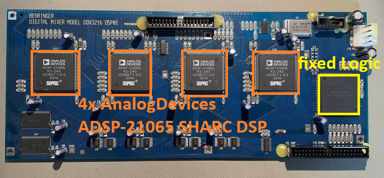
As the DDX3216 has several PIC16-microcontrollers with proprietary firmwares, we probably will not be able to get all parts up and running. I thought about bringing the AnalogDevices SHARC DSPs under my control as I gained some experiences on the Behringer X32 with the 21379 DSPs, but the four SHARC DSPs are connected to proprietary logic-device, comparable to an FPGA, but only on-time-programmable. Without specific information about this device, the connection to the DSPs will be quite hard.
So, I think I will play with FreeDOS a bit more, connect the AT-XT-keyboard-converter and maybe implement the graphic-video-mode to test Windows 2.0 or 3.0 with this device, but only when I have lot of time.
The full sourcecode can be found here on GitHub: https://github.com/xn—nding-jua/DDX3216. There I prepared some DIY bootsector-programs that are able to switch to the protected mode as well to use flat 32-bit-pointers to address the full memory much easier. But with these bootsectors you could not boot DOS as it requires the real-mode of the x86 CPU.